Sonntag, 16. November 2014

Capacitance measurement using the Charge-Transfer-Acquisition-Principle

Some time ago, I read in a magazine about a technique to measure tiny variations in capacitance. I don't remember the name of the magazine, so I cannot give any reference to it. My attempts to google for it were not successful either. Finally, I decided to give it a try.
Edit: Just now I read in the "ELV journal 5/2014 p.47" that this technique is called "Charge-Transfer-Acquisition-Principle". It is mainly used in connection with capacitive touch buttons. ST www.st.com builds controllers for this kind of applications. Search for "capacitive touch" on their website.

This is how it is supposed to work:
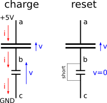
Figure 1: principle of capacity measurement
Two capacitors, a small one (the one that is to be measured) and a larger one (the reference), are connected in series. The idea is: Charge the larger capacitor in several steps, using a current that has to flow through the small capacitor as well. The small one will build up a reverse voltage much quicker than the large one. The current will stop. Reset the small capacitor by shorting it. Repeat the charge-reset cycle and count how many cycles are needed to "fully" charge the large capacitor. The smaller the small capacitor is, the more cycles are needed.


It might be difficult to make absolute measurements of capacitance with this technique. But that is not needed if only variations in capacitance are of interest. The first application that comes to mind are capacitive touch buttons. I believe there are many other interesting things that can be done with this.
In that article, the procedure was realized by connecting the tree points of the circuit to I/O pins of a microcontroller.

I connected the points a,b and c in Fig. 1 to the ATMEGA8 at pins PC2, PC1 and PC0 respectively. As large cap, I used 145 nF (multimeter measurement), and  for the small one I use a 10 nF.
The rest is done in the firmware. The program has to switch the three pins to the right sequence. I consider the big capacitor to be "full" when the voltage (after discharging the small one) at point a is recoginzed as "high" by the microcontroller.
To initialize a new measurements, both capacitors have to be discharged. this is ensured by putting all three points to GND and wait a bit:

// discharge both caps
PORTC &= ~((1<<PC0) | (1<<PC1) | (1<<PC2)); // PORTC = ?????000
DDRC |= (1<<DDC0) | (1<<DDC1) | (1<<DDC2); // DDRC = ?????111
_delay_us(50);


After this, I go to the reset step in Fig. 1: b and c connected to GND (shorted) and a configured as input. A has to be configured as input (high impedance) to prevent it from loosing any charge. 
DDRC ^= (1<<DDC2);
After initializing, the charge and reset states have to be repeated until the big cpacitor is full. The chargin step is achieved by the following:
  • disconnect b from GND (make it an input)  DDRC ^= (1<<DDC1);
  • connect point a to +5V (VCC), i.e. set it to 1 PORTC ^= (1<<PC2); Note that point a is still an input, but writing 1 to the PORTC:2 bit enables the pull-up resistor which is charging the two capacitors
  • wait until the small capacitor is full, i.e. point b is above the threshold to be deteced as high PORTC ^= (1<<PC2);
Going back to "reset" is done by:
  • disconnect the pull-up connection to VCC from point a. This prevent the big capacitor from loosing any charge PORTC ^= (1<<PC2);
  • put point b to GND to discharge the small capacitor, as it was done at the end of the initialization DDRC ^= (1<<DDC1);
All these steps are just done by swapping the correct bits in either PORTC or DDRC using XOR operations.

After each charge-reset cycle, one can test if the big capacitor is already charged, i.e. if point a is 1:
(PINC & (1<<PC2)); // condition to end the measurement

Here are the voltage traces of point a and point b on the oscilloscope:
Figure 2: The voltages at point a (purple) and point b (blue)

Fig. 2 shows all cycles of one measurement. Each spike is one cycle. One can see how the lower end of the purple (point a) line is higher after each cycle because the big capacitor carries more and more charge. Nine cycles are needed to complete the measurement. The bigger the difference between the two capacitors, the more cycles are needed and the more sensitive is the measurement. 
The technique really works nicely and reliably. However, measuring 10 nF can be still done with my multimeter. But this method scales down to much smaller capacitors. I tried a 10 nF as big capacitor, and nothing at all as small capacitor ( there is the capacitance of the breadboard lines): I could see difference in number of cycles by putting a 2pF capacitor.
It is nice to have an oscilloscope to see what is going on. If You don't have one, you can output the number of cycles as a binary number, using LEDs. 

The hardware is trivial (no picture this time). Here is the complete firmware:


#define F_CPU 1000000
#include <avr/io.h>
#include <util/delay.h>

// 
// PC2 -----|
//          |
//      =========    large capacitor
//          |
// PC1 -----+
//          |
//         ===       small capacitor
//          |
// PC0 -----|
//

void initialize()
{
 // discharge both caps
 PORTC &= ~((1<<PC0) | (1<<PC1) | (1<<PC2));
 DDRC  |= (1<<DDC0) | (1<<DDC1) | (1<<DDC2);
 _delay_us(50);

 // go to state: reset (discharge small cap)
 DDRC ^= (1<<DDC2);
 // now:
 //  DDRC  = 0b?????011
 //  PORTC = 0b?????000
}
void cycle()
{
 // assume:
 //  DDRC  = 0b?????011
 //  PORTC = 0b?????000

 // go to state: charge (large cap through small cap)
 DDRC  ^= (1<<DDC1);
 // now:
 //  DDRC  = 0b?????001
 //  PORTC = 0b?????000
 PORTC ^= (1<<PC2);
 // now:
 //  DDRC  = 0b?????001
 //  PORTC = 0b?????100
 while (!(PINC & (1<<PC1)));

 // go back to state: reset
 PORTC ^= (1<<PC2);
 DDRC  ^= (1<<DDC1);

}

int main(void)
{
 DDRD  |= (1 << DDD0);
 //PORTD |= (1 << PD0);
 while(1)
 {
  // create trigger for oscilloscope visualization
  PORTD ^= (1 << PD0);

  initialize();

  int cycles;
  for (cycles = 0; !(PINC & (1<<PC2)); ++cycles) cycle();

  // create trigger for oscilloscope visualization
  PORTD ^= (1 << PD0);

  _delay_ms(10);
 }
 
 return 0 ;
}

Montag, 10. November 2014

Interrupts: The Basics

Introduction

Writing programs for PCs rarely involves contact with the underlying hardware. The operating system provides a layer between the application programmer and the hardware (the processor). Special functionality, for example detecting keys being pressed, is normally provided through libraries.

On microcontrollers such as the ATMEGA, operating systems are rarely used. The firmware interacts directly with the functionality provided by the processor. One important feature of most (if not all) processors is the ability to interrupt the normal program flow if a special condition occurs.

One example: The ATMEGA8 has a pin called INT0. If the controller is set up correctly, pulling the INT0 pin low, for example with a switch that connects it to GND, the normal program flow is interrupted. The program directly jumps to a special function, the interrupt handler routine. If that function returns, the program flow continues where it was before the interrupt happened.

Another example of an interrupt is the overflow of an internal counter. Each interrupt condition has a function that is called whenever that condition occurs. The ATMEGA8 has 19 different interrupts. They are all listed on page 46 in the manual.

I wanted to have a very simple example to get some practice in how to use interrupts. My goal was to change the status (on/off) of a LED whenever the INT0 pin is pulled to ground (by a switch). The program consists of

  • setup of INT0 interrupt and LED output
  • endless loop that does nothing
  • interrupt handler that switches the LED state

INT0 Setup

Finding out how to set up things in the microcontroller can be tedious, if you're using a feature for the first time. It often involves setting/clearing special bits in special registers in a specific order. Which ones to set is documented in the manual and it is good to read relevant sections at some point. For INT0 setup, the key sections of the manual are summarized is this picture:
First, bits 0 and 1 in the MCU control register (MCUCR) have to be cleared to select a level trigger. That means the interrupt is generated whenever the INT0 pin is pulled down. If the interrupt handler routine is done, and the INT0 pin is still low, the interrupt will be triggered again. 
(The default values for both bits is 0, so clearing them could be skipped if one can somehow make sure that they haven't been set somewhere in the program)

Second, bit 6 in the General Interrupt Control Register GICR has to be set to 1 to enable the INT0 interrupt. 

Third the "sei" instruction has to be called, to enable interrupts. 

First Attempt

Here is the full code:

#define F_CPU 1000000
#include <avr/io.h>
#include <avr/interrupt.h>
#include <util/delay.h>

// interrupt handler for INT0
ISR(INT0_vect)
{
 PORTC ^= (1 << DDC0);   // swap the LED state
}

int main(void)
{
 // interrupt setup
 GICR  |= (1<<INT0);                  // enable INT0;
 MCUCR &= ~((1<<ISC01) | (1<<ISC00)); // INT0 low level trigger
 sei();              // enable global interrupt
 DDRD  = 0;          // all PD pins configured as input   
 PORTD = (1 << PD2); // enable pull-up on the INT0 pin    

  // LED setup
 DDRC  = (1 << DDC0); // enable PC0 as output
 PORTC = (1 << DDC0); // switch pin on (LED on)

  while(1)
 {
  // spin forever with 1 MHz
 }

  return 0 ;
}

After the setup of the INT0 interrupt, I've enabled the pull-up resistor for the corresponding pin (PD2). I encourage you to test what happens if this is not done.
In addition, PC0 (where the LED is connected to) is configured as output and turned on.
The program enters an endless while-loop and can only temporarily escape if an interrupt is triggered and the ISR(INT0_vect) function is called.

The hardware looks like this. The switch is realized by a piece of wire... and is a bit tricky to operate, but it works.

Second Attempt

This works, but maybe not as intended. As long as the switch is closed, the green LED blinks very fast, because the interrupt routine is called again and again. There are different ways to achieve a single change of the LED whenever the switch is closed once. One way is to prevent the interrupt handler routine to return as long as the the interrupt condition is still true:

ISR(INT0_vect) 
{
 PORTC ^= (1 << DDC0);   // swap the LED
 // prevent interrupt handler from finishing
 _delay_ms(100);              // not good !!!
 while(!(PIND & (1 << PD2))); // not good !!!
 _delay_ms(100);              // not good !!!
}

The additional delays are there to allow the signal to reach a stable state (stop bouncing), see my rotary encoder post. This one will works as expected. 
But there is a big downside. The run time of this interrupt handler routine is not determined. If one would do that in an application that does more things than only turning a LED on/off, holding the switch would freeze the complete program. No other interrupts can be triggered as long as the INT0 interrupt hanlder didn't return. As a general rule: interrupt handlers should be executed as fast as possible

Third Attempt

There are, again, many ways to solve this. I've tried this: Let the interrupt handler just change the state of a global variable. The state of that variable is then checked in the main loop:

uint8_t swap  = 0;
ISR(INT0_vect) 
{
 swap = 1; // make interrup handler as short as possible
}

The modified while loop:

 while(1)
 {
  if (swap == 1)
  {
   PORTC ^= (1 << DDC0); // swap the led state
   GICR  &= ~(1<<INT0);  // disable INT0
   _delay_ms(100); 
   while(!(PIND & (1 << PD2)));
   _delay_ms(100); 
   swap = 0;
  }
  set_sleep_mode(SLEEP_MODE_IDLE); // select the desired sleep mode
  GICR  |= (1<<INT0);  // enable INT0
  sleep_mode();        // go to sleep
 }

The interrupt should not be triggered again before the switch is opened. It can be deactivated by clearing the INT0 bit in the GICR register. INT0 is enabled again, just before going to IDLE state. INT0 is able to wake up the controller from IDLE state. IDLE state means, that the program flow is stopped and no further instruction is executed.

Final Notes

I am not an expert in this, and all these examples are probably not "best practice". But I hope they illustrates some points about interrupts and help others to get started without diving too deep into the ATMEGA8 manual.
I think that it quickly gets interesting if multiple interrupts are enabled. I have never done this but whenever I do, I plan to share my experiences.

Samstag, 8. November 2014

Rotary Encoder

Rotary knobs are used as input device for embedded systems. Typically, the knob turns a potentiometer or, especially for digital systems, a rotary encoder. Rotary encoders can be turned left/right in discrete steps and will send corresponding pulses over two wires whenever that happens. I wanted to get a rotary encoder running with an ATMEGA8.

Here is a picture of a rotary encoder. I extended the contacts with pieces of wire to mount the encoder on a bread board:


Rotary encoders typically have 3 connectors, one goes to GND, the other two A and B carry the information if the knob was turned and to what direction (left/right). The following picture tries to illustrate what happens:


If the two outputs A and B are hooked up to digital input pins of the microcontroller, it should be possible to write a program that detects these two patterns and does different things for a left and right turn. I will explain further down what the different states are, when I discuss the firmware implementation.

Rotary encoders are mechanical switches, and all mechanical switches have the problem that the signal looks not always as nice as I've drawn it it in the picture. I've done a measurement with my oscilloscope to visualize this. Here is the setup:


The center pin is connected to GND while the A and B connectors are tied to VCC with pull-up resistors. On the right picture the scope probes are visible. They tab the signal at A and B.

Turning the knob gives the following picture on the scope:
The first picture shows the overall signal and looks similar to the ideal one, except that the edges are not very clean. Zooming into one of the edges shows the trace bouncing around before getting to GND level. That has to be taken into account when writing the software for the decoding of the signal.

Hardware

To visualize the effect or turning the knob I've use 4 LEDs. The program has an internal counter that counts from 0 to 3. Turning the knob left counts up, turning it right counts down. The LED indicate at which position the counter is. The final hardware setup to test the rotary encoder can be seen in the following picture. The connections to the programmer are exactly as in my earlyer "Getting Started" post.
And here you can see it in motion:


Firmware

Naively, one could just try to check for a transition of A from high to low while B is low to detect a left turn, and a transition of B from high to low while A is low for the other direction. This doesn't work reliably because of the bouncing of signals.
Instead, the firmware is implemented as a state machine with states corresponding to the ones indicated in the schematic drawing in the beginning of this post. The state machine starts in state 0 and a transition to 1 can only be induced by B going from high to low. If A goes from high to low in state 0, the state machine would go to state 4 (going backwards). Being in state 1, a transition of B from low to high would go back to state 0,  whereas a transition of A from high to low would lead to state 2. The knob was turned by one step if the state makes a full cycle from 0 to 0. The machine is implemented as a big switch() statement. Here is the code:


int8_t rotEnc(uint8_t *state, uint8_t pin, uint8_t bitA, uint8_t bitB)
{
 uint8_t A = pin & (1<<bitA);
 uint8_t B = pin & (1<<bitB);
 
 switch(*state)
 {
  case 0:
   if (!B) {
    *state = 3;
    return -1;
   }
   if (!A) {
    *state = 1;
    return 0;
   }
  case 1:
   if (A) {
    *state = 0;
    return 0;
   }
   if (!B) {
    *state = 2;
    return 0;
   }
  case 2:
   if (B) {
    *state = 1;
    return 0;
   }
   if (A) {
    *state = 3;
    return 0;
   }
  case 3:
   if (!A) {
    *state = 2;
    return 0;
   }
   if (B) {
    *state = 0;
    return  1; 
   }
 }
 return 0;
}


The function takes a pointer to the state, a PIN register and two numbers indicating at which pins the A and B encoder outputs are connected. In my case (A=PC2, B=PC0) , the pin argument is PINC, bitA = 2 and bitB = 0.
The function returns 1 or -1 if a full cycle through the states is completed, 0 otherwise.
The main function is simple. The variable cnt is increased/decreased whenever the rotEnc function detects the completion of a full cycle through the all states. The state has to be stored in the main function. That makes the rotEnc function reusable if there are multiple rotary encoders connected to the microcontroller.


int main(void)
{
 // enable the LED ouputs
 DDRD = (1 << PD0) | (1 << PD1) | (1 << PD2) | (1 << PD3);

 DDRC = 0; // port C as input
 PORTC = (1 << PC0) | (1 << PC2); // enable pull-ups for PC0 (A) and PC2 (B)
 
 int16_t cnt = 0;
 uint8_t state = 0;
 
 while(1)
 {
  cnt += rotEnc(&state,PINC,2,0);

  if (cnt > 3) cnt = 0;
  if (cnt < 0) cnt = 3;
  
  PORTD = (1 << cnt);
 }

 return 0 ;
}

That was an example that used digital I/O for the task of user interaction. 

Input Output

This second post is about digital in and output (short: I/O), i.e. on/off-switching of ATMEGA8 pins, or checking if pins are at high or low potential.
"high", "on", "VCC", "1" are the same in this contex, as well as "low", "off", "GND", "0". They refer to the two different electrical potentials or logic levels in the digital ciruit. (VCC=Voltage Common Collector, GND=ground).

More details about I/O are all described in the ATMEGA8 datasheet, but I try to provide the minimum information to get things done. The notion of "minimum" is of course purely subjective.

Output:

Driving a pin high or low means that the controller internally connects it either to VCC or GND, respectively. The controller has a set of pins that can be driven high or low: The general purpose I/O lines. Groups of 8 pins are controlled by 3 registers (DDRx, PORTx, PINx) each. A register is a special 8bit value in the processor. There are 23 I/O pins controlled by 9 registers: DDR[B,C,D], PORT[B,C,D] and PIN[B,C,D].

In the last post, I've made an LED blink by making the pin PD0 of the controller.  For each I/O pin, the corresponding bit in the DDRD register (DDRD:0 = least significant bit, or 0-th bit, of register DDRD) decides if it is used as input (DDRD:0 = 0) or output (DDRD:0 = 1).
To power a LED, a driven output is needed. The DDRD:0 bit can be set by writing the value 1 in the register
DDRD = 1; // the 8 bits of DDRD are: 00000001
Names such as DDRD are defined in the <avr/io.h> header file.
The previous statement also sets all the other bits of DDRD to 0. If the other bits should be preserved in whatever state they are, one can use the following syntax (I assume familiarity with bitwise operators here):
DDRD |= 1;
Likewise one could make the pin PD3 and output by writing
DDRD |= 8; // the bits of DDRD are: 00001000 (binary representation of 8)
To make the code more readable, it is good practice to use the following notation:
DDRD |= (1 << DDD3); // (1<<DDD3) is same as (1<<3)
Setting two bits of a register can be done like this (set bits 0 and 3 of DDRD to 1):
DDRD |= (1<<DDD0)|(1<<DDD3);
To drive the B-pins or C-pins, one has to write to DDRB and DDRC, respectively.
If DDRD:0 is set to 1, the pin PD0 is high if PORTD:0 is 1 and pin PD0 is low if PORTD:0 is 0.
Changing a pin can be done by XOR operation (as shown in the previous post):
PORTD ^= 1;
Or to make it more readable:
PORTD ^= (1 << PD0);

Input:

To check if a pin is high or low, one has to check the bit-content of the registers PIN[B,C,D]. Reading from PORT[B,C,D] will not work.
To check if pin PD0 is high or low one has to check bit PIND:0 like this
if (PIND & 1)
{
    // PD0 is high.
}
else
{
    // PD0 is low.
}
Or like this to make it more readable:
if (PIND & (1<<PD0)) { //...

If a pin (PD0) is configured as input (DDRD:0 = 0), the value of PORTD:0 specifies if a pull-up resistor is connected (PORTD:0 = 1) or not connected (PORTD:0 = 0) to the pin.
The pull-up connector ensures that in case of no external signal on the pin, reading the pin-bit will give 1. The only way to read a 0 from that pin is, if it is externally driven low (for example by a connection to GND via a push button).


Getting started

I recently started to play more seriously with the ATMEGA8 microcontroller from atmel. The same device runs on the Arduino boards. Since I like doing things from scratch, I prefer to play with the bare microcontroller. In this blog I'll share my experiences. Another intention is the following: The ATMEGA8 device is very well documented in the datasheet. But reading tens of pages to know how to enable a timer or the ADC is tedious, especially for beginners. I intend to go through different features of the ATMEGA8 and provide minimal programs to enable and use them.

In order to get started, a programmer is necessary. That is not the case if you have an Arduino board.
I own a programmer from Tuxgraphics.org. Their webpage contains lots of ATMEGA related information and electronics in general. The programmer I bought was a kit that I needed to solder. Also the firmware wasn't installed on the device. But one can load the firmware to it without having a programmer. I it is very interesting to see how it works.

However, building a kit is tedious if you just want to get started with playing. Tuxgraphics.org offers assembled programmers as well. But if you are short on money, you can find lots of (incredibly) cheap offers for programmers on ebay. I recently bought an USBasp programmer from a Chinese manufacturer for about 4 EURO. I donated a bit of money to the inventor of hard and firmware. I think it is fair and it supports the open hardware and open source movement.

All you need in addition is a breadboard, one ATMEGA8 controller in a DIP (dual in-line) package that you can place on the board and some wires plus all components you want to control (such as an LED and a ~500 ohms resistor). No soldering required at all.

The "hello world" in microcontroller programming is a blinking LED. I will show how to do this in this first post.
My programmer has a 10pin adapter. The basic wiring is like this:
The LED is connected from VCC through a 220 ohm resistor to the PD0 pin of the controller.

If the hardware is set up, the controller can be programmed with a firmware. To create the firmware, I write programs in C. To get them compiled and copied to the controller I need C-compiler and a programming software. I use Linux and the packages "avr-gcc" (compiler) "avrdude" (programming software).

The program that makes the LED blink (blink.c) looks like this:

#include <avr/io.h>
#define F_CPU 1000000UL  // 1 MHz
#include <util/delay.h>

int main(void)
{
 DDRD = 1;
 while(1)
 {
  _delay_ms(200);
  PORTD ^= 1;
 }
}

To get this program running on the microcontroller, three steps are neede:

1. Compiling
avr-gcc -mmcu=atmega8 -Os blink.c
The flag -mmcu=atmega8 informs the compiler about the target arcitecture. -Os optimizes for size of the resulting program.
The result of this call is a file "a.out" which has to be converted to a .hex file that can be copied to the program memory of the controller. 

2. Converting
avr-objcopy -O ihex a.out blink.hex
The flag -O ihex specifies the desired output format and the resulting file is "blink.hex"

3. Loading
avrdude -p m8 -c usbasp -U flash:w:blink.hex
copies the program to the controller, where -p m8 specifies the target device (or part), -c usbasp is my programmer and -U flash:w:blink.hex specifies the program data.
If the last command doesn't work you may not have access to the USB device. The simplest way to solve this is to become root before loading the firmware.

If a LED is connected, it should start blinking now. If everything is working, the door is open to the fascinating world of embedded programming!