Donnerstag, 16. Juni 2016

Serial Peripheral Interface (SPI) and 74HC595

Introduction

Sometimes, the ATMEGA8 has not enough GPIO pins. Typical situation might be if several 7-segment LED display digits are used. Shift register ICs, like the 74HC595, can be used to overcome this limitation. This device can take a serial stream of 8 bits and output them in parallel on its 8 output pins.
In this post I want to show how to use the ATMEGA8 SPI (serial peripheral interface) hardware to control a single 74HC595.
In a SPI communication between a master and a slave, the master always provides the clock signal. I'm using the ATMEGA8 as SPI master. The SPI slave is looking at the clock signal line and the data line, and reads the value of the data line on each clock edge.
The SPI master can also receive data back from the slave over a third connection, but I will not show this here. A lot of ICs use the SPI interface for communication. Examples are sensors, external memory chips, ADC/DAC chips, etc. Also the programming of the ATMEGA8 flash memory is done using its SPI interface.

74HC595

The 74HC595 functionality is described in its datasheet (google for it). It has 5 relevant control inputs. I will permanently connect the OE (output enable) pin to GND, so it is always enabled, and I'm left with 4 signals that have to be controlled actively. These are

  • SER       serial input signal
  • SRCLK shift register clock
  • RSCLR shift register clear
  • RCLK   output register clock

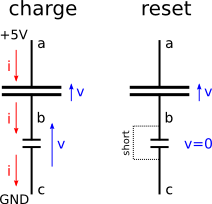
The device (SPI slave in this case) will sample the SER input on each rising edge of the SRCLK input and shift it into its internal register. This works only while the SRCLR input is high. In order to transfer the value in the shift register to the output pins, a rising edge on the RCLK is needed. The transfer of 8 bits can be seen in the following picture.


ATMEGA8 SPI setup

The SPI hardware of the ATMEGA8 creates the clock signal on the SCK pin (alternative function of pin PB5), and the serialized bit stream on the MOSI "master out slave in" pin (alternative function of pin PB3). For the other two control lines of the 74HC595 chip (SRCLR and RCLK) I use pins PB5 and PB1 on the ATMEGA8. The SPI hardware can be enabled and configured in the software by setting some bits in the SPCR (SPI Control Register).


I use the three marked bits to enable the SPI hardware (SPE), change the byte ordering to transmit the least significant bit first (DORD, for data order), and to use the SPI in master mode (MSTR). The transmission is initiated by writing an 8-bit value into the SPDR (SPI Data Register). The end of the transmission is indicated by the SPI hardware if the SPIF bit in the SPSR register is set by the SPI hardware. Here is the complete program:
#include <avr/io.h>
#include <util/delay.h>
#include <stdint.h>

// define connections of 74HC595 input pins to ATMEGA8
#define P_SRCLR PB2
#define P_SER   PB3
#define P_RCLK  PB1
#define P_SRCLK PB5

void write_byte_SPI(uint8_t value)
{
 
 PORTB &= ~(1<<P_SRCLR); // clear register
 PORTB |=  (1<<P_SRCLR); // register can take data
 
 //SPI Data Register – SPDR
 SPDR = value;               // write byte
 while(!(SPSR & (1<<SPIF))); // wait for end of transmission
 
 PORTB &= ~(1<<P_RCLK); // register clock low
 PORTB |=  (1<<P_RCLK); // register clock high 
                        //    will write data to output buffers
}

int main(void) 
{
 // Set SCK MOSI MISO and SS as output
 DDRB = (1<<P_SRCLR)|(1<<P_SER)|(1<<P_RCLK)|(1<<P_SRCLK);

 //SPI Control Register – SPCR
 // Enable SPI, change data order and set to master mode
 SPCR = (1<<SPE)|(1<<DORD)|(1<<MSTR);

 for (uint8_t i = 1;;++i)
 {
  write_byte_SPI(i);
  _delay_ms(300);
 }
}

The setup uses 8 LEDs to display the state of the 74HC595 output pins. There are only 4 pins of the ATMEGA8 used to control 8 LEDs (display the value of counter variable i in binary form). That is why this is also called "port extension". By chaining multiple 74HC595 chips, one can control almost any number of LEDs. In the picture, the ATMEGA8 can be seen on the top right, connected by the 4 wires to the 74HC595 chip on the bottom.


Montag, 23. Mai 2016

TWI (or I2C) communication

Introduction

The I2C protocol is used for communication between different parts (up to 127 participants) of a system using only two wires. I will show a very simple example with two ATMEGA8 microcontrollers that communicate via this protocol. Atmel calles this not I2C, but TWI (two wire interface). A detailed description is on page 157 of the ATMEGA8 datasheet. It is quite long and there are many ways of using the TWI interface. It takes a bit of time reading the section and understand what is going on. The example here can be used as a "quickstart" guide into this protocol and to get some working code as a starting point for own implementations.
The following picture shows the topology of a TWI network: all participants are connected to two wires that are held at VCC potential by two pull-up resistors. There is a clock line (SCL) and a data line (SDA). Communication happens always between exactly two participants at one time (with the exception of a general call, but I'll not describe that). The participant that initiates the communication is called "master" and adresses another participant which is called "slave". As part of each transmission, the master has to sent the address of the slave. All slaves are continuously monitoring their TWI lines and have to react if their address is called.

modified picture from the ATMEGA8 datasheet, showing the layout of my small example with one master and one slave, indicated in red
My example will be the following: one ATMEGA8 measures an analog voltage level with it's ADC and transmit the information over a TWI connection to another ATMEGA8 for visualization. The measuring ATMEGA8 will provide the data as a TWI slave and I give it the address 0x01. The displaying ATMEGA8 will be the master and initiates the transmission. In this configuration, my TWI slave will always be in a "slave transmit" mode, and my master will always be in a "master receive" mode. Other combinations "slave receive" and "master transmit" are also possible, but I want to keep the example small.
I will use the TWI in connection with interrupts, so some basic knowledge of interrupt mechanisms is needed to understand this example.
The following picture shows a schematic drawing of my setup. I didn't draw the connections to the ISP programmer. Note that the two devices really are only connected by the power lines and the two TWI wires (in blue).  I used ADC3 input to connect a variable voltage divider. To keep things simple, I only transmit a single byte over the TWI interface. The two least significant bits from the 10-bit ADC value are truncated and only the 8 most significant bits are transferred. The reset pins of both controllers are connected to ensure that both start working at the same time.


The implementation on a bread board looks like this:


Relevant TWI Registers

The TWI subsystem in the ATMEGA8 is controlled by some registers. These are described on pages 165-167 of the datasheet.
The TWI Bit Rate Register (TWBR) contains a divisor for the clock frequency and determines the TWI clock speed. I leave that register untouched, which will result in a TWI clock speed that is 1/16 of the CPU clock speed.

The TWI Control Register (TWCR) is used to enable the TWI hardware (set TWEA bit to 1) and is also used to interact with the hardware between transmission actions (via the TWINT bit). In TWI tranmissions, the control is passed back and forth between the user application program and the TWI hardware on the chip. The application code has to set some bits in that register according to what the next TWI action should be. After setting the TWINT bit, the TWI hardware starts working again - independent from the application code. It will first clear the TWINT bit. Whenever the TWI hardware is done with its actions, it sets the TWINT bit again. The application code can either poll that bit to check when the TWI hardware is done, or it can request an interrupt that is triggered by the TWI hardware. In this example I've chosen the latter possibility.
If the application code is notified by the TWINT bit in the TWCR register, it can obtain the status of the TWI hardware from the TWS[3:7] bits in the TWI Status Register (TWSR).
For all four operation modes of the TWI interface (master transmit, master receive, slave transmit, slave receive) the application code has a finite number of options. All of them are listed in the ATMEGA8 datasheet in tables.

After the TWINT bit was set (and an interrupt was triggered) the application code might find the number 0xA8 in the TWS[3:7] bits. The table lists all the possible options, which are chosen by setting or clearing certain combination of bits in the TWSTA, TWSTO and TWEA bits in the TWCR register. After setting the desired action, the TWI hardware is activated again by setting the TWINT bit again. Given the tables for all four communication modes, there are many many ways of realizing communication between two TWI devices. Often, the slave will be a given part (e.g. a sensor with I2C interface) and its behavior will be documented in its datasheet. Using an ATMEGA8 to read such a sensor requires to implement the correct a master behavior. In this demonstration example, both devices will be ATMEGA8. I have implemented a very simple (might be the simplest possible) slave behavior in the following code.

Slave Transmitter Program

When the TWI was addressed, the interrupt routine ISR(TWI_vect) is called, and the switch statement will go to the first case. The transmission data is loaded into the TWI Data Register (TWDR) and the first row of the above table is chosen, i.e. indicating the last data byte. In the case of only one data byte, the first byte is also the last.
After sending the byte, the TWI hardware will get the acknowledge signal from the master. Then, the TWEA bit has to be set again which tells the TWI hardware to monitor the address line and trigger another interrupt if its address is called. The transferred data is generated by the ADC, using only the 8 most significant bits of the 10-bit ADC value.
#include <avr/io.h>
#include <avr/interrupt.h>

#define F_CPU 1000000UL  // 1 MHz
#include <util/delay.h>
#include <util/twi.h>

#define SLAVE_ADDRESS (0x01)

uint8_t adc_value; // the value to send

// interrupt routine for TWI message handling
ISR(TWI_vect)
{
  // react on TWI status and handle different cases
  uint8_t status = TWSR & 0xFC; // mask-out the prescaler bits
  switch(status)
  {
    case TW_ST_SLA_ACK:   // own SLA+R received, acknoledge sent
         TWDR = adc_value;
         TWCR &= ~((1<<TWSTO) | (1<<TWEA));
    break;
    
    case TW_ST_LAST_DATA: // last byte transmitted ACK received     
         TWCR |= (1<<TWEA); // set TWEA to enter slave mode
    break;
    }
    TWCR |= (1<<TWINT);  // set TWINT -> activate TWI hardware
}

int main(void)
{
  // TWI setup
  sei(); // enable global interrupt
 
  // set slave address to 0x01, ignore general call
  TWAR = (SLAVE_ADDRESS << 1) | 0x00;
  // TWI-ENable , TWI Interrupt Enable
  TWCR |= (1<<TWEA) | (1<<TWEN) | (1<<TWIE); 
    
  // ADC setup
  ADCSRA |= (1<<ADEN);
  ADMUX  |= ( (1<<REFS1) | (1<<REFS0) ); // select internal reference
  ADMUX  |= 3;   // select channel 5 (pin ADC5)
 
  // infinite loop
  for (;;)
  {
    ADCSRA |= (1<<ADSC);        // start single measurement
    while(ADCSRA & (1<<ADSC));  // wait until measurement done
    
    // read result bytes (low and high) and reduce to 8-bits
    adc_value = ADCL;
    adc_value >>= 2;          // drop 2 least significant bits
    adc_value |= (ADCH << 6); // add two most significant bits
  }
}

Master Receiver Program

Another ATMEGA8 is loaded with the following program that can obtain the ADC value from the slave transmitter described above. The transmission is initialized by setting the TWSTA bit in the TWCR register. This only makes sense if there is no other transmission in progress, as indicated by the ongoing_transmission global variable. If the transmission is initiated, the address of the slave is given by the content of the data register in the first case of the switch statement: the 7 most significant bits of the TWDR register contain the address, while the least significant bit is 1 for a reading action and 0 for a writing action (from the perspective of the master). In this example we are a master receiver and we want to read. Our TWDR content is thus (SLAVE_ADDRESS << 1) | 0x01;
In the next TWI interrupt, we have the confirmation of the slave that it has acknowledged our call. We say that we want to acknowledge after receiving the data in the next TWI action (the TWEA bit remains set). After the next interrupt, the data is available in the TWDR data register. The only thing left to do is to send a stop condition by setting the TWSTO bit.
In the first and last case of the switch statement, the ongoing_transmission variable is managed to indicate to the main program that a transmission is ongoing.
#include <avr/io.h>
#define F_CPU 1000000UL  // 1 MHz
#include <util/delay.h>

#include <avr/interrupt.h>
#include <util/twi.h>

#define SLAVE_ADDRESS (0x01)

uint8_t value; // contains the received value

uint8_t ongoing_transmission = 0;

// interrupt routine for the timer0 overflow interrupt
ISR(TWI_vect)
{
  // react on TWI status and handle different cases
  uint8_t status = TWSR & 0xFC; // mask-out the prescaler bits
  switch(status)
  {
    case TW_START:  // start transmitted
         ongoing_transmission = 1;
         // write SLA+R, SLA=0x01
         TWDR = (SLAVE_ADDRESS << 1) | 0x01;
         TWCR &= ~((1<<TWSTA)); // clear TWSTA
    break;
  
    case TW_MR_SLA_ACK: // SLA+R transmitted, ACK received 
         TWCR &= ~((1<<TWSTA) | (1<<TWSTO)); 
    break;
  
    case TW_MR_DATA_ACK: // data received, ACK returned
         ongoing_transmission = 0;
         value = TWDR;
         TWCR |= (1<<TWSTO);  // write stop bit
         TWCR &= ~(1<<TWSTA); // clear start bit
    break;
  }
  TWCR |=   (1<<TWINT);  // hand over to TWI hardware
}

int main(void) 
{
  // TWI setup
  sei(); // enable global interrupt
  // TWI-ENable , TWI Interrupt Enable
  TWCR |= (1<<TWEA) | (1<<TWEN) | (1<<TWIE); 

  // LED setup
  DDRB  = 0x3f; // PORTB[0:5] as output
  DDRC  = 0x03; // PORTC[0:1] as output
 
  for (;;) // infinite main loop
  {
    // initiate new transmission if 
    //    no transmission is in progress
    if (!ongoing_transmission) TWCR |= (1<<TWSTA); 
 
    PORTB = value;    // display number
    PORTC = value>>6; //   as LED pattern 
  }
}


Bus Action

Finally, a look at the TWI bus lines with the oscilloscope to see what is going on:

The upper signal is the SCL line, the bottom signal is the SDA line. Both lines are high if nothing is happening because of the pull-up resistors.
Start and stop conditions are indicated by a SDA change while SCL is high. During address and data transmissions, the SCL line goes high when the transmitter has a stable voltage level on the SDA line so that the receiver can sample the voltage level. The first burst of 9 clock pulses is during the 7-bit address transmission (plus read bit and acknowledge bit) from the master to all TWI participants. The second burst of clock pulses is the transmission and acknowledge of the data byte.

More

The example here is minimal, and not robust against failures on the TWI bus. A proper implementation would have to handle all cases that are describe in the four mode tables of TWI operation. Otherwise the TWI hardware might get stuck.
I also didn't mention at all the possibility of multiple masters on one TWI bus. There is a way of preventing bus collisions if two masters signal a start condition at the same time. 
There is the possibility that one master addresses all participants at the same time in a so called general call.

Samstag, 21. Mai 2016

Analog Digital Conversion (ADC)

Introduction

In many applications, analog voltages are involved, and the actions of the microcontroller should depend on a given analog voltage level (for example a data logger). In order to convert it into a digital value (i.e. a binary number), analog to digital converters (ADCs) are used. The ADC compares the measured voltage to a reference voltage. The resulting number will be the ratio of the measured voltage and the reference voltage, where a ratio of 1 or greater would be mapped to the highest possible 10-bit value (0b1111111111), and 0 or smaller would be mapped to the lowest value (0b0000000000). The ATMEGA8 has an integrated 10-bit ADC that is connected to 6 of the pins in the DIP package (marked red in the following picture). Here I present a small setup and some C code that demonstrates how the ADC can be used.

Setup

A schematic drawing of the setup is shown in the next picture. Relevant pins of the ATMEGA are labeled. The connections to the programmer (also serving as power supply) are shown in blue. Note that the programmer can stay connected all the time and will not interfere with the operation of the circuit.
The voltage divider is connected to the ADC5 pin. 10 LEDs are used to display the binary value of after the analog to digital conversion. The AVCC pin has to be powered in this example (connected to VCC). Previous examples, not using the ADC, didn't need that pin. If low noise is important, the AVCC power rail should be a separate extra low noise power supply.

There are 3 sources for the ADC reference voltage for the ATMEGA8: the supply voltage, a voltage provided at the AREF pin, or an internal 2.56V reference.
I will use the internal reference. In this case a capacitor has to be connected tot the AREF pin. If you build that circuit, I encourage you to disconnect that capacitor and see what happens to the output: it will be completely random.

Firmware

As always, making use of the ADC requires to write the correct values to the right registers, and as always, everything is well documented in the ADC section of the datasheet. The following program will measure the voltage from a variable resistor divider with the ADC and use the value to switch some LEDs that will show the binary representation of the measured ADC value.

The relevant section of the ATMEGA8 datasheet starts on page 189. There are two registers that need to be manipulated to get the ADC running: ADCSRA and ADMUX (described on pages 199 & 200 in the datasheet)


The program will do the ADC setup and enter an infinite loop, in which it measures the voltage at ADC5 pin and displays the value on the LEDs. The LED on pin PC3 has the most significant bit of the 10-bit value, and PB0 has the least significant bit.

Setting the ADEN bit in ADCSRA register to 1 enables the ADC subsystem
ADCSRA |= (1<<ADEN);

The voltage reference is selected by the two bits REFS1 and REFS0 in the ADMUX register. Table 74 on page 199 of the datasheet shows, that both bits have to be set in order to get the internal voltage reference.
ADMUX |= ( (1<<REFS1) | (1<<REFS0) );

Since I connected my analog signal to ADC5, the number 5 has to be written to the MUX[0:3] part of the ADMUX register
ADMUX |= 5;

A conversion is started by setting ADSC bit to 1 in the ADCSRA register. If the conversion is done, the ADC sets this bit back to 0.
ADCSRA |= (1<<ADSC);        
while(ADCSRA & (1<<ADSC)); // wait until conversion is done

The result is then available in the registers ADCL and ADCH, which can be combined to a single 10-bit value (of course stored in a 16-bit integer).
uint16_t value;
value = ADCL; 
value |= (ADCH<<8); 

The complete program

#include <avr/io.h>
#define F_CPU 1000000UL  // 1 MHz
#include <util/delay.h>

int main(void)
{
  // enable ADC
  ADCSRA |= (1<<ADEN);
  ADMUX |= ( (1<<REFS1) | (1<<REFS0) ); // internal reference
  ADMUX |= 5;                           // select ch. 5 (pin ADC5)
 
  // LED setup
  // PORTB[0:5] as output
  DDRB  = 0x3f; // 0011 1111
  // PORTC[0:2] as output
  DDRC  = 0x0f; // 0000 1111
 
  for (;;) 
  {
    uint16_t value;

    ADCSRA |= (1<<ADSC);        // start single measurement
    while(ADCSRA & (1<<ADSC));  // wait until measurement done

    // read result bytes (low and high)
    value  = ADCL;
    value |= (ADCH<<8);
  
    // display number
    PORTB = value;
    PORTC = value>>6;
  }
}

Finally, some pictures of my setup, showing three different settings of the voltage divider. A multimeter is connected to the ADC input voltage to verify the ATMEGA8 measurement. The 10-bit value can be seen on the right hand side with the least significant bit on the lowest LED and the most significant bit on the top LED.


More

This example is intended to get you started. The ATMEGA8 ADC can do more. For example the sampling frequency can be adjusted using the ADPS[0:2] bits in the ADCSRA register. The ADC can be configured to trigger interrupts and it can operate in a noise cancellation mode. All this is described in detail in the ADC section of the datasheet.

Montag, 1. Dezember 2014

Serial Interface (USART)

A microcontroller alone is already a cool thing. But it becomes even more useful, if it is coupled to a PC. Think about the capacitance measurement example of my previous post. I needed an oscilloscope to see what is happening and to count the number of charge-reset cycles. It would be very convenient to send the number of cycles to the PC for logging or further analysis.

The ATMEGA8 microcontroller has several ways of sending and receiving data. This post is about sending data to the pc using it's Universal Synchronous and Asynchronous serial Receiver and Transmitter (USART). This can be used to send data to the "serial port" of a PC. A detailed description of the USART functionality of the controller is in the ATMEGA8 datasheet. As always I recommend to read the section at some point. I'll give just enough information to get something running.

Physical Connection

One "problem" of nowadays PC is, that they frequently have no serial port connector. The second problem is: Even if they do, the serial port specifications work with 15V logic levels, we run our controller with 5V.
The first problem can be solved with USB to serial adapters (Fig. 1), like the one I have.
Figure 1: My USB to serial adapter cable
The second problem (15V logic levels) can be visualized by measuring the outgoing signal from the PC using an oscilloscope. The probe has to be connected to the pin 3 of the sub-d 9 connector. Pins 2 and 3 are the relevant ones for the signal reception and transmission, respecively. (Complete pin assignment can be found in the web, google for "sub-d 9 serial" or something similar)

Figure 2: conecting the scope probe to the transmission line of the PC
From the PC, it is very simple to send some data over the serial port. I can open a shell and type:  echo a > /dev/ttyUSB0
This sends the letter 'a' over the serial line. Fig. 3 shows what I see on the scope screen:
Figure 3: the picture seen when typing: echo a > /dev/ttyUSB0
Note, that the y-axis has 5V per divison. The signal amplitude is indeed 15V. In addition, the signal looks quite noisy (the rightmost side of the signal trace in Fig. 3: looks like a saw-tooth signal).

As a consequence of the high voltage, a converter (or "level adapter") is needed. There are special ICs for that purpose, for example the MAX232 (which I've never used). However, doing so, would result in a chain with 2 adapter devices:

PC -> USB-serial -> level-adapter -> ATMEGA8

For the following experiments, I used instead this device from www.tuxgraphics.org/. It is adds USB connectivity to this power supply, but it can be used as a generic USB serial adapter / level converter / optical decoupling. It is very nice kit, because the data transfer is done optically (no electrical noise on the transfer lines and no ground loops). USB interface is done using the ft232rl chip from FTDI.

The setup with the adapter from tuxgraphics looks like this:
Figure 4: Setup with the optically coupled USB-serial converter from tuxgraphics. The inset shows what can be seen on the scope when sending the (hexadecimal) number 0x55 to the device by typing echo -ne '\x55' > /dev/ttyUSB0 in the terminal
The signal looks nice and clean with 5V amplitude.

The Protocol

What is the computer sending? If not active, the output (visible on the scope in Fig. 4) of the PC is on high level (5V). If a transmission is starting, the PC output gets low (0V). That happens always, independent of the number that is to be send. Then follow 8 bits of data. Then one stop bit (high). The number 0x55 happens to be 01010101 in binary representation. The transmission starts with the least significant bit, which is a '1' which is transmitted as high level (5V).
There is no clock line that indicates to the receiver, when to sample the data line for the bits. Consequently, the transmission can only be successful, if transmitter and receiver agree on the bit-rate. There is a large variety of options available for setting up serial port on a PC. But the default (just echo some data to /dev/ttyUSB0 device) seems to be a rate of 9600 BAUD. 1 BAUD is one bit per second. With the "transmission-initialize" bit at the beginning, we transmit 10 bits (1 start, 8 data, 1 stop bit). 10 bits at 9600 bits per second makes a byte-length of 10/(9600 bits/sec)=0.96ms per byte. That is exactly what can be seen on the scope. 

The Firmware

Now I want to set-up the ATMEGA8 to receive that signal. Without any prior knowlege, one has to read the full section about the USART device in the controller manual. Here I provide the setup to comunicate with a PC with default settings:

First, the USART device has to be set up. This works (as always) by setting the correct bits in the correct registers of the controller.
The BAUD rate is determined by a 16-bit value in the UBRRH and UBRRL registers, where both of them contain one half of the 16-bit number. There is a formula in the ATMEGA8 datasheet to calculate the ubrr-value for a given clock frequency and a given BAUD rate. In addition (page 155), there is a table with commonly used configurations.
I want 9600 at 8MHz, so the value is 51.
The next step is to enable the receiver and transmitter, which works by setting the corresponding bytes in the UCSRB register (page 149). 
Then I set the data format to 8 data bits and 1 stop bit, using the UCSRC register (see page 150 and the following tables on page 151 and 152.

The receiver is always on and looks for data. If an outside transmission was received, this is indicated by the RXC-bit in the UCSRA register. If that bit is set to 1, the received value is accessible in the UDR register.

Transmitting simply works by writing the message-byte into the UDR register. But before, one should check if the transmitter is not busy by looking at the UDRE-bit in the UCSRA register.

All these things are done in the following program, which waits for a transmission. If it receives the character 'a', it sends back the message "hello, world!".
It can be used by starting a program like "picocom" on the PC. this program captures key presses and sends the characters using the serial port specified as command line argument. It also displays any data that the PC serial receiver gets.
Just type picocom /dev/ttyUSB0 on the command line and press keys on the keyboard. After pressing 'a', "hello, world!" should come as an answer.
Quit picocom by pressing Ctrl-a Ctrl-x.

#define F_CPU 8000000
#include <avr/io.h>
#include <util/delay.h>

int main(void)
{
  //init serial receiver
  uint16_t ubrr = 51;          // BAUD rate is 9600  at 8 MHz
  UBRRH = (uint8_t)(ubrr>>8);  // high byte of ubrr
  UBRRL = (uint8_t)ubrr;       // low byte of ubrr

  // Enable receiver and transmitter 
  UCSRB = (1<<RXEN)|(1<<TXEN);

  // Set frame format: 8 data-bits, 1 stop-bit 
  UCSRC = (1<<URSEL)|(3<<UCSZ0);

  while(1)
  {
    while ( !(UCSRA & (1<<RXC)) ); // wait for serial transmission
    uint8_t ch = UDR;              // get the transmitted byte from UDR register
  
    if (ch == 'a')
    {
      char msg[] = "hello, world!";
      char *ptr = msg;
      do
      {
        while ( !( UCSRA & (1<<UDRE)) ); // wait for output to be free
        UDR = *ptr++; // writing data into register initiates transmission
      } while (*ptr);
    }
  }
  return 0 ;
}

Sonntag, 16. November 2014

Capacitance measurement using the Charge-Transfer-Acquisition-Principle

Some time ago, I read in a magazine about a technique to measure tiny variations in capacitance. I don't remember the name of the magazine, so I cannot give any reference to it. My attempts to google for it were not successful either. Finally, I decided to give it a try.
Edit: Just now I read in the "ELV journal 5/2014 p.47" that this technique is called "Charge-Transfer-Acquisition-Principle". It is mainly used in connection with capacitive touch buttons. ST www.st.com builds controllers for this kind of applications. Search for "capacitive touch" on their website.

This is how it is supposed to work:
Figure 1: principle of capacity measurement
Two capacitors, a small one (the one that is to be measured) and a larger one (the reference), are connected in series. The idea is: Charge the larger capacitor in several steps, using a current that has to flow through the small capacitor as well. The small one will build up a reverse voltage much quicker than the large one. The current will stop. Reset the small capacitor by shorting it. Repeat the charge-reset cycle and count how many cycles are needed to "fully" charge the large capacitor. The smaller the small capacitor is, the more cycles are needed.


It might be difficult to make absolute measurements of capacitance with this technique. But that is not needed if only variations in capacitance are of interest. The first application that comes to mind are capacitive touch buttons. I believe there are many other interesting things that can be done with this.
In that article, the procedure was realized by connecting the tree points of the circuit to I/O pins of a microcontroller.

I connected the points a,b and c in Fig. 1 to the ATMEGA8 at pins PC2, PC1 and PC0 respectively. As large cap, I used 145 nF (multimeter measurement), and  for the small one I use a 10 nF.
The rest is done in the firmware. The program has to switch the three pins to the right sequence. I consider the big capacitor to be "full" when the voltage (after discharging the small one) at point a is recoginzed as "high" by the microcontroller.
To initialize a new measurements, both capacitors have to be discharged. this is ensured by putting all three points to GND and wait a bit:

// discharge both caps
PORTC &= ~((1<<PC0) | (1<<PC1) | (1<<PC2)); // PORTC = ?????000
DDRC |= (1<<DDC0) | (1<<DDC1) | (1<<DDC2); // DDRC = ?????111
_delay_us(50);


After this, I go to the reset step in Fig. 1: b and c connected to GND (shorted) and a configured as input. A has to be configured as input (high impedance) to prevent it from loosing any charge. 
DDRC ^= (1<<DDC2);
After initializing, the charge and reset states have to be repeated until the big cpacitor is full. The chargin step is achieved by the following:
  • disconnect b from GND (make it an input)  DDRC ^= (1<<DDC1);
  • connect point a to +5V (VCC), i.e. set it to 1 PORTC ^= (1<<PC2); Note that point a is still an input, but writing 1 to the PORTC:2 bit enables the pull-up resistor which is charging the two capacitors
  • wait until the small capacitor is full, i.e. point b is above the threshold to be deteced as high PORTC ^= (1<<PC2);
Going back to "reset" is done by:
  • disconnect the pull-up connection to VCC from point a. This prevent the big capacitor from loosing any charge PORTC ^= (1<<PC2);
  • put point b to GND to discharge the small capacitor, as it was done at the end of the initialization DDRC ^= (1<<DDC1);
All these steps are just done by swapping the correct bits in either PORTC or DDRC using XOR operations.

After each charge-reset cycle, one can test if the big capacitor is already charged, i.e. if point a is 1:
(PINC & (1<<PC2)); // condition to end the measurement

Here are the voltage traces of point a and point b on the oscilloscope:
Figure 2: The voltages at point a (purple) and point b (blue)

Fig. 2 shows all cycles of one measurement. Each spike is one cycle. One can see how the lower end of the purple (point a) line is higher after each cycle because the big capacitor carries more and more charge. Nine cycles are needed to complete the measurement. The bigger the difference between the two capacitors, the more cycles are needed and the more sensitive is the measurement. 
The technique really works nicely and reliably. However, measuring 10 nF can be still done with my multimeter. But this method scales down to much smaller capacitors. I tried a 10 nF as big capacitor, and nothing at all as small capacitor ( there is the capacitance of the breadboard lines): I could see difference in number of cycles by putting a 2pF capacitor.
It is nice to have an oscilloscope to see what is going on. If You don't have one, you can output the number of cycles as a binary number, using LEDs. 

The hardware is trivial (no picture this time). Here is the complete firmware:


#define F_CPU 1000000
#include <avr/io.h>
#include <util/delay.h>

// 
// PC2 -----|
//          |
//      =========    large capacitor
//          |
// PC1 -----+
//          |
//         ===       small capacitor
//          |
// PC0 -----|
//

void initialize()
{
 // discharge both caps
 PORTC &= ~((1<<PC0) | (1<<PC1) | (1<<PC2));
 DDRC  |= (1<<DDC0) | (1<<DDC1) | (1<<DDC2);
 _delay_us(50);

 // go to state: reset (discharge small cap)
 DDRC ^= (1<<DDC2);
 // now:
 //  DDRC  = 0b?????011
 //  PORTC = 0b?????000
}
void cycle()
{
 // assume:
 //  DDRC  = 0b?????011
 //  PORTC = 0b?????000

 // go to state: charge (large cap through small cap)
 DDRC  ^= (1<<DDC1);
 // now:
 //  DDRC  = 0b?????001
 //  PORTC = 0b?????000
 PORTC ^= (1<<PC2);
 // now:
 //  DDRC  = 0b?????001
 //  PORTC = 0b?????100
 while (!(PINC & (1<<PC1)));

 // go back to state: reset
 PORTC ^= (1<<PC2);
 DDRC  ^= (1<<DDC1);

}

int main(void)
{
 DDRD  |= (1 << DDD0);
 //PORTD |= (1 << PD0);
 while(1)
 {
  // create trigger for oscilloscope visualization
  PORTD ^= (1 << PD0);

  initialize();

  int cycles;
  for (cycles = 0; !(PINC & (1<<PC2)); ++cycles) cycle();

  // create trigger for oscilloscope visualization
  PORTD ^= (1 << PD0);

  _delay_ms(10);
 }
 
 return 0 ;
}

Montag, 10. November 2014

Interrupts: The Basics

Introduction

Writing programs for PCs rarely involves contact with the underlying hardware. The operating system provides a layer between the application programmer and the hardware (the processor). Special functionality, for example detecting keys being pressed, is normally provided through libraries.

On microcontrollers such as the ATMEGA, operating systems are rarely used. The firmware interacts directly with the functionality provided by the processor. One important feature of most (if not all) processors is the ability to interrupt the normal program flow if a special condition occurs.

One example: The ATMEGA8 has a pin called INT0. If the controller is set up correctly, pulling the INT0 pin low, for example with a switch that connects it to GND, the normal program flow is interrupted. The program directly jumps to a special function, the interrupt handler routine. If that function returns, the program flow continues where it was before the interrupt happened.

Another example of an interrupt is the overflow of an internal counter. Each interrupt condition has a function that is called whenever that condition occurs. The ATMEGA8 has 19 different interrupts. They are all listed on page 46 in the manual.

I wanted to have a very simple example to get some practice in how to use interrupts. My goal was to change the status (on/off) of a LED whenever the INT0 pin is pulled to ground (by a switch). The program consists of

  • setup of INT0 interrupt and LED output
  • endless loop that does nothing
  • interrupt handler that switches the LED state

INT0 Setup

Finding out how to set up things in the microcontroller can be tedious, if you're using a feature for the first time. It often involves setting/clearing special bits in special registers in a specific order. Which ones to set is documented in the manual and it is good to read relevant sections at some point. For INT0 setup, the key sections of the manual are summarized is this picture:
First, bits 0 and 1 in the MCU control register (MCUCR) have to be cleared to select a level trigger. That means the interrupt is generated whenever the INT0 pin is pulled down. If the interrupt handler routine is done, and the INT0 pin is still low, the interrupt will be triggered again. 
(The default values for both bits is 0, so clearing them could be skipped if one can somehow make sure that they haven't been set somewhere in the program)

Second, bit 6 in the General Interrupt Control Register GICR has to be set to 1 to enable the INT0 interrupt. 

Third the "sei" instruction has to be called, to enable interrupts. 

First Attempt

Here is the full code:

#define F_CPU 1000000
#include <avr/io.h>
#include <avr/interrupt.h>
#include <util/delay.h>

// interrupt handler for INT0
ISR(INT0_vect)
{
 PORTC ^= (1 << DDC0);   // swap the LED state
}

int main(void)
{
 // interrupt setup
 GICR  |= (1<<INT0);                  // enable INT0;
 MCUCR &= ~((1<<ISC01) | (1<<ISC00)); // INT0 low level trigger
 sei();              // enable global interrupt
 DDRD  = 0;          // all PD pins configured as input   
 PORTD = (1 << PD2); // enable pull-up on the INT0 pin    

  // LED setup
 DDRC  = (1 << DDC0); // enable PC0 as output
 PORTC = (1 << DDC0); // switch pin on (LED on)

  while(1)
 {
  // spin forever with 1 MHz
 }

  return 0 ;
}

After the setup of the INT0 interrupt, I've enabled the pull-up resistor for the corresponding pin (PD2). I encourage you to test what happens if this is not done.
In addition, PC0 (where the LED is connected to) is configured as output and turned on.
The program enters an endless while-loop and can only temporarily escape if an interrupt is triggered and the ISR(INT0_vect) function is called.

The hardware looks like this. The switch is realized by a piece of wire... and is a bit tricky to operate, but it works.

Second Attempt

This works, but maybe not as intended. As long as the switch is closed, the green LED blinks very fast, because the interrupt routine is called again and again. There are different ways to achieve a single change of the LED whenever the switch is closed once. One way is to prevent the interrupt handler routine to return as long as the the interrupt condition is still true:

ISR(INT0_vect) 
{
 PORTC ^= (1 << DDC0);   // swap the LED
 // prevent interrupt handler from finishing
 _delay_ms(100);              // not good !!!
 while(!(PIND & (1 << PD2))); // not good !!!
 _delay_ms(100);              // not good !!!
}

The additional delays are there to allow the signal to reach a stable state (stop bouncing), see my rotary encoder post. This one will works as expected. 
But there is a big downside. The run time of this interrupt handler routine is not determined. If one would do that in an application that does more things than only turning a LED on/off, holding the switch would freeze the complete program. No other interrupts can be triggered as long as the INT0 interrupt hanlder didn't return. As a general rule: interrupt handlers should be executed as fast as possible

Third Attempt

There are, again, many ways to solve this. I've tried this: Let the interrupt handler just change the state of a global variable. The state of that variable is then checked in the main loop:

uint8_t swap  = 0;
ISR(INT0_vect) 
{
 swap = 1; // make interrup handler as short as possible
}

The modified while loop:

 while(1)
 {
  if (swap == 1)
  {
   PORTC ^= (1 << DDC0); // swap the led state
   GICR  &= ~(1<<INT0);  // disable INT0
   _delay_ms(100); 
   while(!(PIND & (1 << PD2)));
   _delay_ms(100); 
   swap = 0;
  }
  set_sleep_mode(SLEEP_MODE_IDLE); // select the desired sleep mode
  GICR  |= (1<<INT0);  // enable INT0
  sleep_mode();        // go to sleep
 }

The interrupt should not be triggered again before the switch is opened. It can be deactivated by clearing the INT0 bit in the GICR register. INT0 is enabled again, just before going to IDLE state. INT0 is able to wake up the controller from IDLE state. IDLE state means, that the program flow is stopped and no further instruction is executed.

Final Notes

I am not an expert in this, and all these examples are probably not "best practice". But I hope they illustrates some points about interrupts and help others to get started without diving too deep into the ATMEGA8 manual.
I think that it quickly gets interesting if multiple interrupts are enabled. I have never done this but whenever I do, I plan to share my experiences.

Samstag, 8. November 2014

Rotary Encoder

Rotary knobs are used as input device for embedded systems. Typically, the knob turns a potentiometer or, especially for digital systems, a rotary encoder. Rotary encoders can be turned left/right in discrete steps and will send corresponding pulses over two wires whenever that happens. I wanted to get a rotary encoder running with an ATMEGA8.

Here is a picture of a rotary encoder. I extended the contacts with pieces of wire to mount the encoder on a bread board:


Rotary encoders typically have 3 connectors, one goes to GND, the other two A and B carry the information if the knob was turned and to what direction (left/right). The following picture tries to illustrate what happens:


If the two outputs A and B are hooked up to digital input pins of the microcontroller, it should be possible to write a program that detects these two patterns and does different things for a left and right turn. I will explain further down what the different states are, when I discuss the firmware implementation.

Rotary encoders are mechanical switches, and all mechanical switches have the problem that the signal looks not always as nice as I've drawn it it in the picture. I've done a measurement with my oscilloscope to visualize this. Here is the setup:


The center pin is connected to GND while the A and B connectors are tied to VCC with pull-up resistors. On the right picture the scope probes are visible. They tab the signal at A and B.

Turning the knob gives the following picture on the scope:
The first picture shows the overall signal and looks similar to the ideal one, except that the edges are not very clean. Zooming into one of the edges shows the trace bouncing around before getting to GND level. That has to be taken into account when writing the software for the decoding of the signal.

Hardware

To visualize the effect or turning the knob I've use 4 LEDs. The program has an internal counter that counts from 0 to 3. Turning the knob left counts up, turning it right counts down. The LED indicate at which position the counter is. The final hardware setup to test the rotary encoder can be seen in the following picture. The connections to the programmer are exactly as in my earlyer "Getting Started" post.
And here you can see it in motion:


Firmware

Naively, one could just try to check for a transition of A from high to low while B is low to detect a left turn, and a transition of B from high to low while A is low for the other direction. This doesn't work reliably because of the bouncing of signals.
Instead, the firmware is implemented as a state machine with states corresponding to the ones indicated in the schematic drawing in the beginning of this post. The state machine starts in state 0 and a transition to 1 can only be induced by B going from high to low. If A goes from high to low in state 0, the state machine would go to state 4 (going backwards). Being in state 1, a transition of B from low to high would go back to state 0,  whereas a transition of A from high to low would lead to state 2. The knob was turned by one step if the state makes a full cycle from 0 to 0. The machine is implemented as a big switch() statement. Here is the code:


int8_t rotEnc(uint8_t *state, uint8_t pin, uint8_t bitA, uint8_t bitB)
{
 uint8_t A = pin & (1<<bitA);
 uint8_t B = pin & (1<<bitB);
 
 switch(*state)
 {
  case 0:
   if (!B) {
    *state = 3;
    return -1;
   }
   if (!A) {
    *state = 1;
    return 0;
   }
  case 1:
   if (A) {
    *state = 0;
    return 0;
   }
   if (!B) {
    *state = 2;
    return 0;
   }
  case 2:
   if (B) {
    *state = 1;
    return 0;
   }
   if (A) {
    *state = 3;
    return 0;
   }
  case 3:
   if (!A) {
    *state = 2;
    return 0;
   }
   if (B) {
    *state = 0;
    return  1; 
   }
 }
 return 0;
}


The function takes a pointer to the state, a PIN register and two numbers indicating at which pins the A and B encoder outputs are connected. In my case (A=PC2, B=PC0) , the pin argument is PINC, bitA = 2 and bitB = 0.
The function returns 1 or -1 if a full cycle through the states is completed, 0 otherwise.
The main function is simple. The variable cnt is increased/decreased whenever the rotEnc function detects the completion of a full cycle through the all states. The state has to be stored in the main function. That makes the rotEnc function reusable if there are multiple rotary encoders connected to the microcontroller.


int main(void)
{
 // enable the LED ouputs
 DDRD = (1 << PD0) | (1 << PD1) | (1 << PD2) | (1 << PD3);

 DDRC = 0; // port C as input
 PORTC = (1 << PC0) | (1 << PC2); // enable pull-ups for PC0 (A) and PC2 (B)
 
 int16_t cnt = 0;
 uint8_t state = 0;
 
 while(1)
 {
  cnt += rotEnc(&state,PINC,2,0);

  if (cnt > 3) cnt = 0;
  if (cnt < 0) cnt = 3;
  
  PORTD = (1 << cnt);
 }

 return 0 ;
}

That was an example that used digital I/O for the task of user interaction.